
Every drives textbook says the same two things: open-loop V/f control is simple but loses speed under load, and closed-loop current-source drives hold speed but pay for it elsewhere. This Electrical Drives (EE4251) project set out to measure that trade instead of reciting it - by building both schemes in Simulink/Simscape Electrical around the same three-phase squirrel-cage induction motor and running them through matched test cases.
A comparison is only worth anything if everything else is held constant. So both models drive the identical machine - the MathWorks preset 4 kW / 400 V / 50 Hz / 1430 rpm motor, with R, L, and J taken from the preset's tabulated values rather than hand-set - and both bridges use the same IGBT/Diode switch blocks, so device losses cancel out of the comparison.
Model A - V/f voltage-source drive
Open-loop scalar V/f control: a 6-pulse diode bridge and LC pre-link feed a DC-DC boost converter regulating the bus to 700 V, into a 3-leg IGBT VSI switching at a 5 kHz SPWM carrier, with low-frequency boost in the V/f law. The boost stage is not decoration - it exists because linear SPWM at m = 1 can only deliver the motor's rated 400 V line-to-line if the DC bus is high enough, and the diode bridge alone cannot get it there.
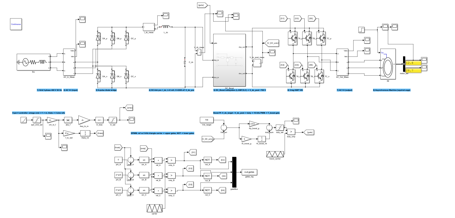
Model A: grid, diode bridge, boost stage, IGBT VSI, and machine (top), with the V/f law, SPWM modulator, and boost PI below.
Model B - CSI drive with slip regulation
The closed-loop counterpart: an alpha-controlled thyristor rectifier and DC-link choke feed a 6-switch current-source inverter. Control follows the canonical "Structure 1" from the lecture notes - an outer speed PI produces the slip-frequency reference, a constant-magnetizing-current map converts it to the DC-link current command, and an inner current PI sets the rectifier firing angle. The inverter fires at the sum of slip and rotor frequency.
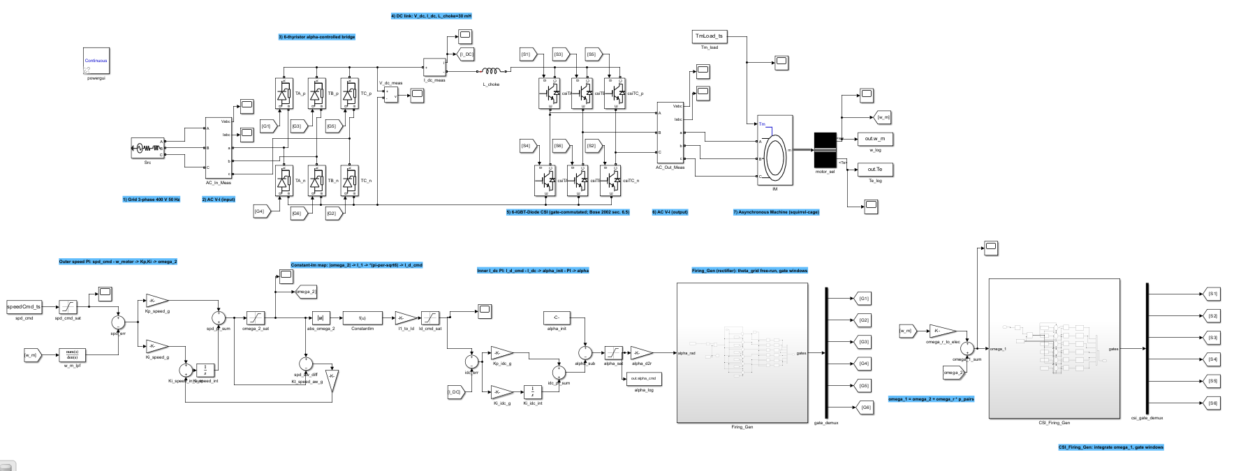
Model B: thyristor rectifier, DC choke, IGBT-based CSI, and machine (top), with the speed PI, constant-I m map, inner current PI, and firing generators below.
Why an IGBT bridge in a "thyristor" drive
The classic textbook CSI is a full thyristor ASCI - 6 thyristors, 6 isolating diodes, 6 commutation capacitors. We deliberately used the gate-commutated IGBT-CSI variant instead, for reasons worth stating:
- The control structure is device-agnostic - the fundamental-current relation it relies on holds for any 6-step current-source bridge.
- At 4 kW, IGBT-CSI is the modern industrial choice; full ASCI hardware lives at hundreds of kilowatts.
- Gate commutation avoids the LC ringing an incomplete ASCI would introduce, and skips 12 extra power components of solver overhead with no pedagogical payoff.
- Most importantly: using the same IGBT/Diode blocks as Model A keeps the V/f-vs-CSI comparison on identical hardware.
Models as code
Neither model was drawn by hand. Build scripts construct the full Simulink diagrams programmatically - build_vf_model.m and build_csi_model.m are the source of truth, with headless .slx companions generated for fresh-session demos. The same script-driven approach runs the whole rig: per-case test runners, FFT/THD analysis, A-vs-B overlay plots, and LaTeX-ready summary tables all regenerate from scratch with a handful of commands. Rebuilding the entire study is a script call, not an afternoon of clicking.
What the measurements showed
Matched test cases (no-load and rated-load at each speed command) put numbers on the textbook trade:
| Pair | rpm cmd | rpm ss A / B | T_e ss A / B (N·m) | i_a THD A / B (%) |
|---|---|---|---|---|
| A1 / B1 (no load) | 1500 | 1499 / 974 | 0.40 / -2.49 | 1.17 / 41.17 |
| A2 / B2 (rated load) | 1500 | 1440 / 1487 | 27.67 / 27.13 | 1.33 / 12.72 |
| A3 / B3 (no load) | 1000 | 999 / 785 | 0.31 / -6.92 | 0.03 / 42.38 |
Read across the rows and the trade appears exactly where theory says it should - with magnitudes theory doesn't give you. At no load, the open-loop V/f drive tracks the command almost perfectly (1499 of 1500 rpm) while the CSI settles far off with heavy current distortion - light load is the CSI's known weak spot. Put rated torque on the shaft and the picture inverts: the V/f drive droops to 1440 rpm because nothing compensates the slip, while the CSI's slip regulation holds 1487 rpm. And the current THD column quantifies the price of current-source operation throughout: roughly 1% for the SPWM VSI against 12-42% for the CSI.
Full per-case results (torque peaks, DC-link voltages, voltage THD) are in the repository's Model A and Model B docs, with full discussion in the report.
References
- EE4251 - Electrical Drives lecture notes (Structure 1 control architecture and constant-I m map).
- Bose, 2002 - Modern Power Electronics and AC Drives: V/f law; thyristor-ASCI and IGBT-CSI topologies.
- Krishnan, 2001 - Electric Motor Drives: Modeling, Analysis, and Control: V/f and CSI cross-references.
- Erickson & Maksimović, 2001 - Fundamentals of Power Electronics: DC-DC boost topology and CCM PI control.
Contributors
For build scripts, models, and the full test harness, visit the GitHub repository.