Maze Solving Robot
Robot capable of maze exploration, path optimization, and line following

This is an autonomous maze solving robot developed for Embedded Systems Design. It combines multiple navigation algorithms, sensor fusion, and path optimization to navigate complex maze environments.
System Architecture
Way-Finder is built around the Arduino Mega 2560 microcontroller and features a modular software architecture with distinct operational modes:
- Microcontroller: Arduino Mega 2560
- Motors: 2 x DC Geared Motors with Quadrature Encoders (360 counts/rev)
- Motor Control: Dual H-Bridge Motor Driver (TB6612/L298N)
- Distance Sensing: 3 x HC-SR04 Ultrasonic Sensors (Front, Left, Right, and additional angles)
- Line Detection: QTR-8A/8RC 8-Channel IR Line Sensor Array
- Power System: 12V 1500mAh Rechargeable Lipo Battery + 5V Buck Converter
- Mode Selection: DIP Switch for operational mode selection
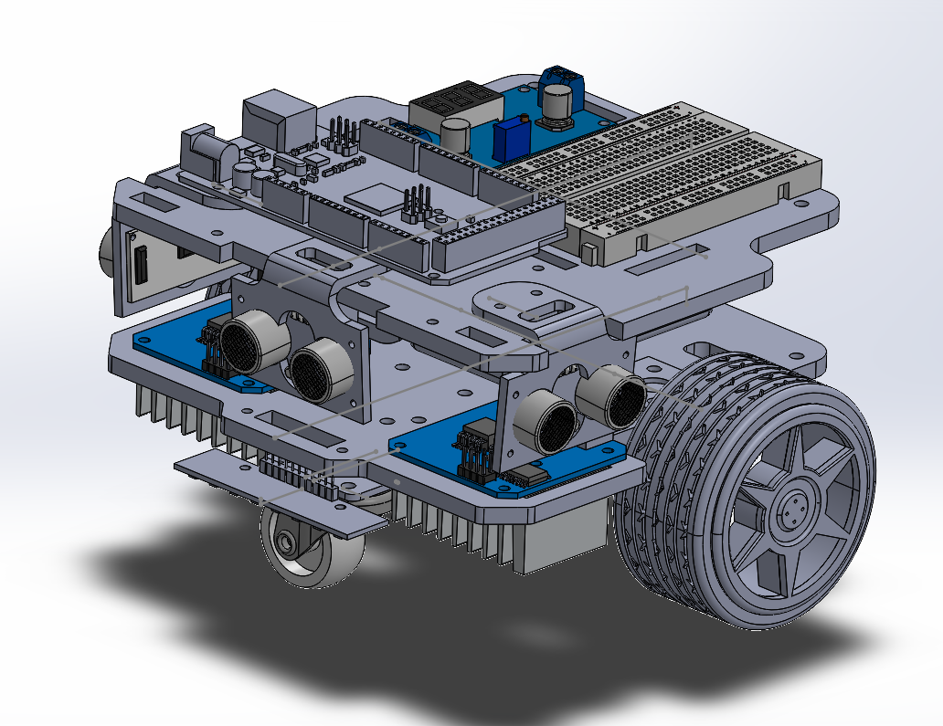
- Mechanical Design: Custom 3D-printed chassis with laser-cut acrylic layers
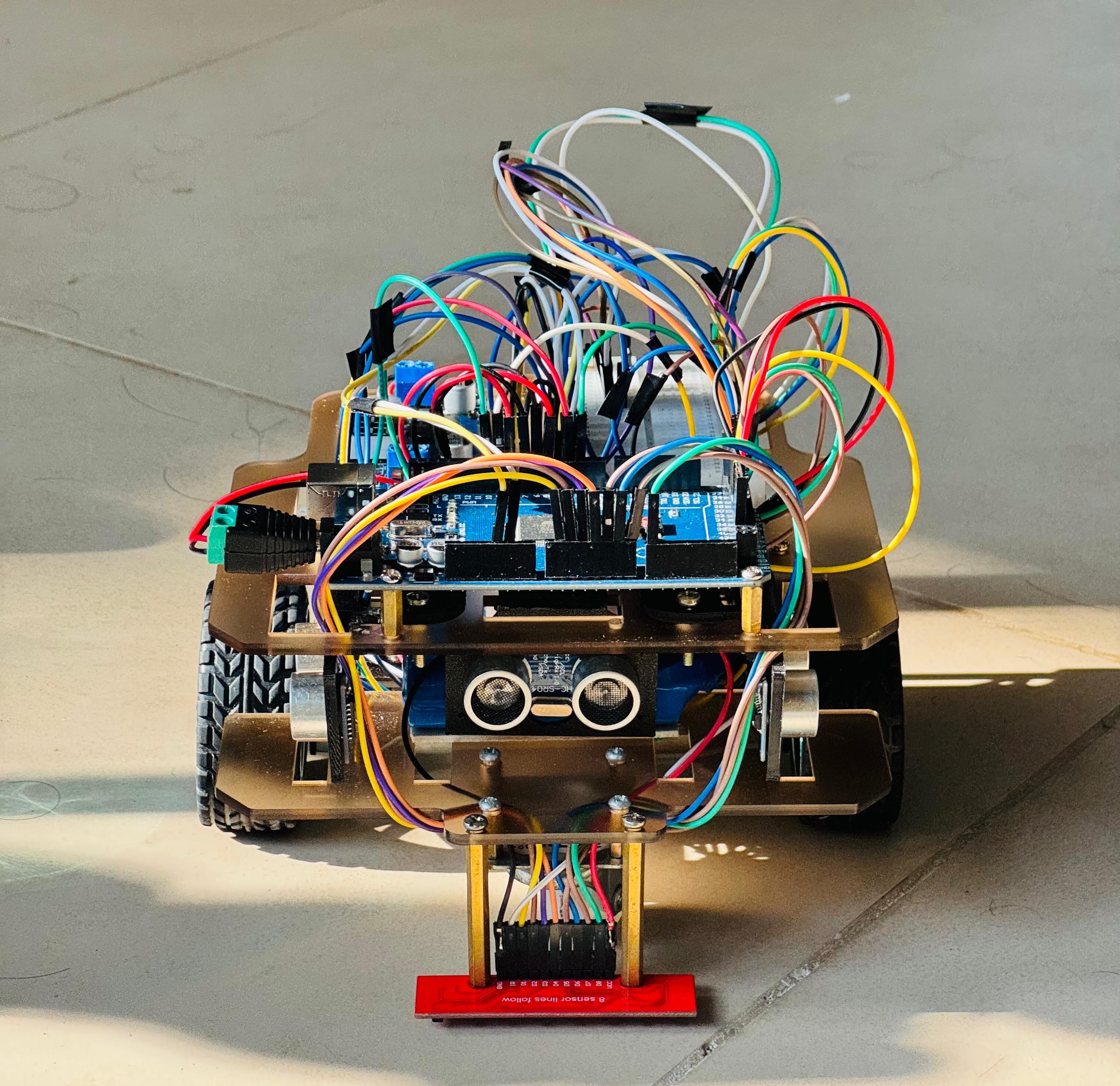
Complete Robot Assembly with Sensor Array
Operational Modes
1. Line-Following Mode
In the line-following mode, the robot operates purely as a high-precision line tracker using an 8-channel IR sensor array and a tightly tuned PID controller. Sensor readings are converted into a weighted positional error, allowing smooth lateral corrections while maintaining forward velocity.
Robot Performing Line Following with PID Control
- Weighted IR-based position estimation with PID control
- Automatic junction and turn detection
- Adaptive speed regulation with error smoothing
2. Wall-Following Mode
The wall-following mode is designed for compact n x n maze environments and relies exclusively on ultrasonic sensing and encoder feedback. Navigation decisions are made at each junction using a consistent wall-following strategy, allowing the robot to traverse the maze without prior knowledge of its structure. Precise encoder-based turns and distance-thresholded wall detection ensure reliable movement between cells while maintaining predictable behavior under tight spatial constraints.
- Ultrasonic-based wall detection with fixed distance thresholds
- Real-time junction decision making
- Encoder-accurate 90° and 180° turns
Robot Performing Wall Following with PID Control
3. Combined Maze Tracking Mode
In the combined maze tracking mode, the robot first navigates a 4 x 4 maze segment using wall-following logic, after which it transitions to line-following to reach the entrance of a larger 9 x 9 maze. Once inside the 9 x 9 maze, the robot performs systematic exploration and registration using a breadth-first search-based tracking strategy, recording wall connectivity and cell transitions. After completing full maze coverage and identifying the goal location, the robot returns to the origin and stores the complete maze representation persistently in EEPROM for later retrieval.
- Sequential navigation across 4 x 4 and 9 x 9 maze domains
- DFS-based maze registration and mapping
- Persistent storage of maze data in EEPROM
Short walkthrough of the robot intial stages
4. Combined Maze Solving Mode
The combined maze solving mode reuses the previously stored maze data to execute an optimized run. The robot again begins in the 4 x 4 maze section, transitions via line-following to the 9 x 9 maze, and loads the stored maze structure from memory. Using a Flood Fill shortest-path computation, distance values are propagated across the maze grid, and the robot follows the resulting path to reach the destination efficiently.
- Stored maze loading and reuse from prior tracking
- Shortest-path computation using Flood Fill
Control Systems
PID Motor Control
The robot employs independent closed-loop PID controllers for the left and right DC motors, using quadrature encoder feedback with a resolution of 360 counts per revolution. Straight-line traversal across a single maze cell (25 cm) is calibrated to 288 encoder ticks, while precise in-place rotations require approximately 116-117 ticks per wheel for a 90° turn and 232-233 ticks for a 180° turn, resulting in turn accuracy within ±2°.
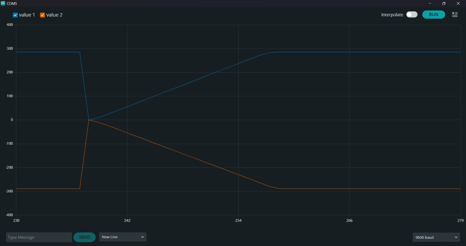
PID Tuning and Calibration Process
Sensor Fusion
- Ultrasonic Sensors: Wall detection and distance measurement (20cm threshold)
- IR Line Array: Tile boundary detection and line following
- Encoder Feedback: Precise position tracking and odometry
Algorithm Implementation
Depth-First Search (DFS)
DFS is used during the exploration phase to autonomously map unknown 9 x 9 maze environments. The robot incrementally explores each available path until a dead end is reached, at which point it backtracks to the nearest unexplored junction.
A stack-based traversal strategy is used to manage visited states and ensure complete maze coverage. Wall information for each cell is recorded in a structured grid representation, allowing the robot to reliably discover the goal location and persist the maze structure in EEPROM with full coverage.
Flood Fill Algorithm
Flood Fill used to compute the shortest path to the goal. Each cell in the maze is assigned a Manhattan distance value relative to the target cell, which is initialized with a distance of zero and propagated outward. During execution, the robot follows a descending gradient of distance values, for optimal path selection.
Mechanical Design
Robot Side View - Showing Sensor Array
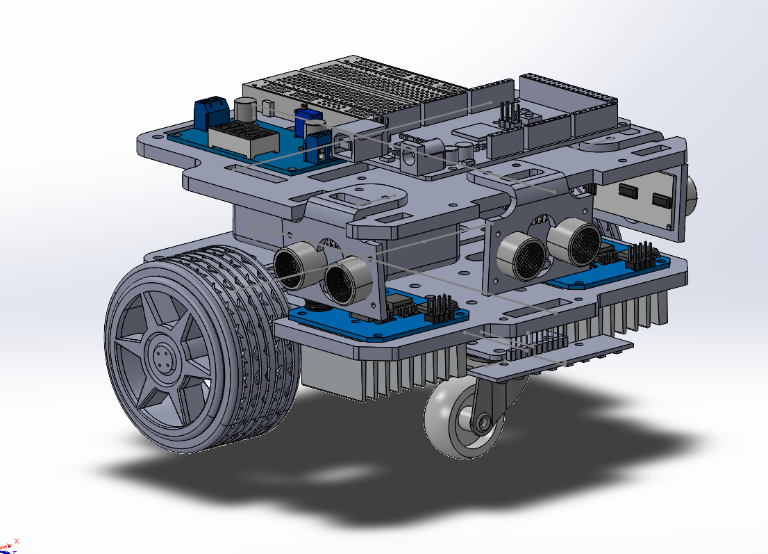
Robot Side View - Motor and Wheel Assembly
The robot features a custom-designed chassis optimized for maze navigation:
- Chassis Material: 3D-printed frame with laser-cut acrylic layers
- Wheelbase: 15.5cm for stable turning
- Wheel Diameter: 6.0cm (65mm robot wheels)
- Ground Clearance: Optimized for smooth maze floor navigation
- Sensor Mounting: Custom 3D-printed ultrasonic holders with 3-5° down-tilt
- Weight Distribution: Battery placement for optimal center of gravity
- Modularity: Two-layer design allows easy access to electronics
Software Architecture
The software system follows a modular and extensible architecture with clear separation of responsibilities.
- Mode Manager: Central state machine for mode selection and transitions
- Algorithm Modules: Independent namespaces for each navigation algorithm
- Utility Functions: Shared motor control, sensor reading, and PID calculation functions
- Constants Management: Centralized configuration for tuning parameters
- EEPROM Manager: Persistent storage with magic number validation
- Interrupt Handlers: Efficient encoder counting with atomic operations
Conclusion
This project provided hands-on experience with real-time control systems, algorithm implementation on resource-constrained platforms, and the challenges of transitioning from simulation to physical hardware.
Contributors
For more details, explore the GitHub repository containing complete source code, mechanical design files, and documentation.